
Yes. Our modules fully comply with the Sinara standard and integrate seamlessly with third-party solutions.
Sinara / ARTIQ Ecosystem for Quantum Technologies
Same challenges, same needs – many flexible solutions: discover the modular Sinara system.

Build Exactly the System You Need
When designing a control and measurement setup, a common challenge is selecting the right electronics for your specific application. Often, a large rack is only partially used, and gaps in the measurement system are filled with temporary—or sometimes costly—solutions. This is exactly why Sinara is gaining worldwide popularity and expanding into research labs around the globe.
FPGA Power, Python Simplicity
Sinara modules are electronic boards in the EEM (Eurocard Extension Module) standard. Each comes with dedicated gateware supported by the ARTIQ software, allowing you to leverage the full potential of FPGAs—much faster than microcontrollers—while programming your experiment directly from Python scripts.
From Signal to System
Sinara boards are designed to provide simple functionality while maintaining top-level performance. Whether you’re controlling 5 or 1000 qubits, you can easily scale your system: simply add more boards and control the experiment from a master board, managing subordinate satellites.
Sinara is open-hardware, giving every user real influence over its development. Today, Sinara is a flagship of the international ion-trap community.
What we Offer:
- Sinara modules
- Training and consultations (from one-hour sessions to multi-day workshops)
- Integrated plug-and-play systems with ready-to-run scripts for experiment control
Why Sinara?
- Modular architecture for rapid, flexible system design
- Precise, low-noise, low-jitter signal control
- Python-scripted experiments
- FPGA-based hardware for high-speed processing
- Easy, cost-effective scaling by adding boards
- Multi-channel readout
- Deterministic timestamp control and real-time operations (microsecond-level)
- Expert support from Creotech Quantum
Use cases
- Qubit control in ion-trap and cold-atom quantum processors
- Quantum metrology
- Quantum detection
- Quantum logic
Users
- Universities and research institutions
- Quantum computing companies
- Military labs (e.g., GPS-denied navigation)
- Technology corporations
What’s Included in Sinara?
A wide range of Eurocard and MTCA modules enables control over every stage of qubit preparation, manipulation, and readout, including:
- FPGA controller with time distribution across the system
- DACs and ADCs – digital-to-analog and analog-to-digital converters
- DDS – digital synthesis for RF signal generation (0–400 MHz)
- TTL – digital inputs and outputs
- AWG – arbitrary waveform generation up to 14 GHz
- RF and DAC-dedicated amplifiers
- Feedback/servo loops – laser modulation and PDH locking
- Stabilizers – magnetic field and temperature control
- Frame grabber – support for sCMOS/CCD camera image acquisition
Modules

Kasli SOC
Device Type: Zynq® XC7Z030 SoC (FPGA + ARM CPU)
RAM: 1 GB DDR3
Processor: Yes (via SoC architecture – integrated CPU + FPGA)
Ethernet Connectivity: 1 × RJ45 100/1000T + 4 × SFP
USB: USB 2.0 (UART, JTAG)
EEM Connectors: 12
Reference Clock: 4 × MMCX, 1 × SMA
Application: Advanced controller – operation of Sinara modules via ARTIQ, enabling complex systems combining CPU and FPGA
Power Supply: +12 V (barrel connector, passed through to EEM)

Kasli v2
Device Type: Artix-7 100T FPGA
RAM: 512 MB DDR3
Processor: No CPU – FPGA only
Ethernet / Optical Connectivity: 3 × SFP (Ethernet / DRTIO)
USB: micro-USB (JTAG, debug, flash)
EEM Connectors: 12
Reference Clock: 4 × MMCX, 1 × SMA
Application: Cost-efficient controller / satellite node in a DRTIO network, FPGA-based control of EEM modules
Power Supply: +12 V (barrel connector, same as Kasli-SOC)

DIO SMA
Channels: 8 I/O (2 banks × 4 channels)
Signal Type: TTL
Connectors: SMA
Direction Control: Per bank (4 channels) via onboard switches or I²C
Termination: Optional passive resistor per channel (anti-reflection)
Output Capability: >2.1 V into 50 Ω load
Output Impedance: 50 Ω
Short-Circuit Protection: Unlimited tolerance
Minimum Pulse Width: 5 ns
Max Switching Frequency: 150 MHz (50% load)
Isolation: Separate isolated ground per bank
Additional Features: LED indicators, selectable termination
Panel Width: 8 HP

DIO BNC
Channels: 8 I/O (2 banks × 4 channels)
Signal Type: TTL
Connectors: BNC
Direction Control: Per bank (4 channels) via onboard switches or I²C
Termination: Optional passive resistor per channel (anti-reflection)
Output Capability: >2.1 V into 50 Ω load
Output Impedance: 50 Ω
Short-Circuit Protection: Unlimited tolerance
Minimum Pulse Width: 5 ns
Max Switching Frequency: 150 MHz (50% load)
Isolation: Separate isolated ground per bank
Additional Features: LED indicators, selectable termination
Panel Width: 8 HP
DIO MCX
Channels: 16 I/O
Signal Type: TTL
Connectors: MCX
Direction Control: 4 channel groups via DIP switch, status via I²C and LED
Termination: Optional 50 Ω termination per channel
Output Capability: 50 Ω capable
Output Impedance: 50 Ω
Isolation: Non-isolated
EEM Connectivity: 2 × EEM connectors (single possible)
Additional Features: LED indicators, compact connectors

DIO RJ45
Channels: Up to 16 LVDS I/O (8 with single EEM)
Signal Type: LVDS
Connectors: RJ45
Direction Control: Per signal via I²C or onboard switches
Termination: 100 Ω differential termination (LVDS)
Output Capability: LVDS differential outputs
Output Impedance: 100 Ω differential
Short-Circuit Protection: Short-circuit protected
Max Switching Frequency: 150 MHz tested (higher possible)
Isolation: Non-isolated
EEM Connectivity: Up to 2 × EEM connectors
Additional Features: SPI-compatible LVDS mapping (optional use)

Urukul AD9910
Main function: DDS RF generator
Frequency range: up to ~400 MHz
Channels: 4 DDS
Frequency resolution: ~0.25 Hz (32-bit)
Phase resolution: 16 bit
Amplitude control: 14-bit digital
Update time: 4 ns
RF outputs: 4 SMA
RF chain features: attenuator + RF switch
Key chips: AD9910 DDS
FPGA: controlled by core device
Typical role: dynamic RF control
Urukul AD9912
Main function: High-precision DDS RF generator
Frequency range: up to ~400 MHz
Channels: 4 DDS
Frequency resolution: ~8 µHz (47-bit)
Phase resolution: 14 bit
Amplitude control: none
Update time: 4 ns
RF outputs: 4 SMA
RF chain features: attenuator + RF switch
Key chips: AD9912 DDS
FPGA: controlled by core device
Typical role: ultra-precise RF generation
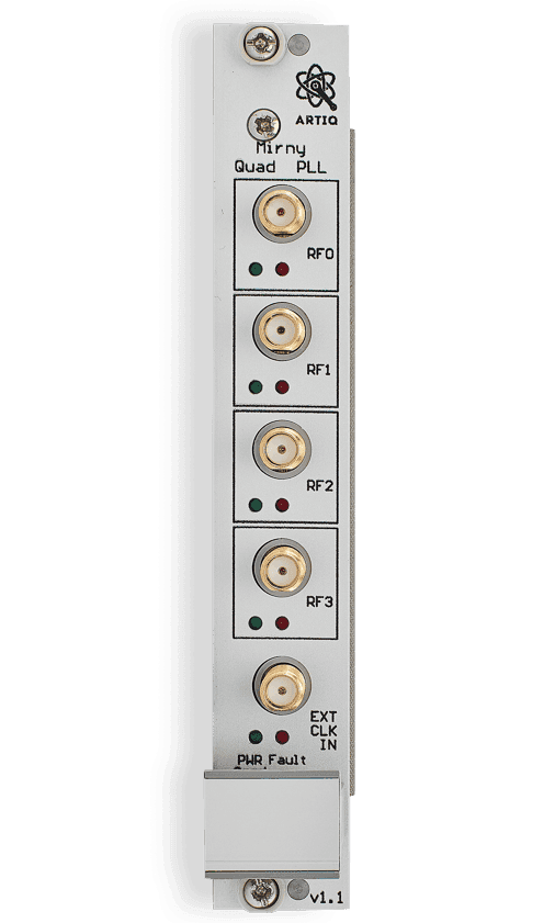
Mirny / Almazny
Main function: Microwave frequency synthesizer
Frequency range: 50 MHz – 4 GHz (up to 12 GHz with Almazny)
Channels typically: 4 PLL channels
Frequency resolution: PLL step dependent
Phase resolution: PLL controlled
Amplitude control: digital attenuation
Update time: slower (PLL tuning)
RF outputs: RF outputs with switches
RF chain features: attenuator, RF switch, amplifiers, filters
Key chips: ADF4355/4356/5355/5356 PLL
FPGA: CPLD routing
Typical role: microwave LO / high-frequency source

Phaser
Main function: Wideband RF signal generator / IQ system
Frequency range: 0.3 – 4.8 GHz (via mixer/VCO)
Channels: 4 RF channels
Frequency resolution: determined by DDS in FPGA
Phase resolution: digital IQ control
Amplitude control: digital attenuator
Update time: deterministic FPGA pipeline
RF outputs: RF outputs via mixers
RF chain features: digital upconversion, IQ mixing
Key chips: FPGA + high-speed DACs
FPGA: Artix-7 FPGA
Typical role: multi-tone RF synthesis
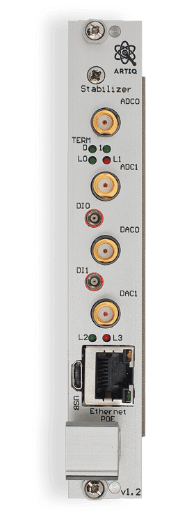
Stabilizer
Main function: Digital feedback controller
Frequency range: depends on connected AFE
Channels: multiple analog IO
Frequency resolution: not a synthesizer
Amplitude control: DAC outputs
Update time: depends on control loop
RF outputs: analog outputs
RF chain features: analog front-end capable
Key chips: STM32H7 + ADC/DAC
FPGA: none (MCU based)
Typical role: feedback control loops
Pounder
Main function: PDH lock RF generator
Frequency range: 1 – 200 MHz
Channels: 4 DDS (AD9959)
Frequency resolution: DDS based
Phase resolution: DDS phase control
Amplitude control: DDS amplitude
Update time: DDS timing
RF outputs: RF outputs
RF chain features: optimized for PDH locking
Key chips: AD9959 DDS
FPGA: relies on Stabilizer
Typical role: Pound-Drever-Hall locking

Fastino
Channels: 32
Resolution: 16-bit
Update Rate: 2.55 MS/s simultaneous, ~1 µs DAC masking
DAC: AD5542ABCPZ, 1 μs settling time
Interface: Dual EEM, 1 Gb/s LVDS, channel masking for reduced crosstalk
Modularity / Connectivity: Lower, optimized for ARTIQ integration
Best Use Case: Maximum simultaneous speed, tight RTIO integration

Zotino
Channels: 32
Resolution: 16-bit
Update Rate: 1 MS/s, arbitrarily divided among channels
DAC: AD5372BCPZ, ±10 V output, 470 Ω + 2.2 nF output impedance
Interface: Single EEM (power + data), HD68/IDC front panel connectors, breakout to BNC/SMA
Power / Thermal: 3 W no load, 8.7 W max load; DAC/reference temperature stabilizable via thermostat
Modularity / Connectivity: High, flexible breakout options for different experimental setups
Best Use Case: Higher output voltage, thermal stability, easy connection to external devices
Sampler BNC
Connector Type: BNC, bayonet (insert + ¼ turn), robust, widely used in labs
Connector Size: Larger, diameter ~14 mm
Impedance / Bandwidth: 50 Ω or 75 Ω, typical bandwidth up to ~4 GHz
Durability: ~500–1000 cycles, solid and robust
Channels: 8
Resolution: 16-bit
Update Rate: Simultaneous 1.5 MS/s per channel
Input Range: ±10 mV to ±10 V
Typical Use: ADC measurements, laser power stabilization, servo with Urukul, lab instrumentation
Mechanical Notes: Bayonet ensures strong mechanical connection, ideal for frequent plug/unplug
Applications: Lab setups, oscilloscopes, analog/digital signals, robust connections
Sampler MCX
Connector Type: MCX, snap-on (press & click), compact, quick to connect
Connector Size: Small, diameter ~3 mm, space-saving
Impedance / Frequency: 50 Ω, typical bandwidth up to ~6 GHz, supports higher frequencies in compact form
Durability / Mating Cycles: ~500 cycles, more delicate
Channel Count: 8
Resolution: 16-bit
Sampling Rate Simultaneous: 1.5 MS/s per channel
Programmable Input Range: ±10 mV to ±10 V
Applications: ADC measurements, laser power stabilization, servo with Urukul, miniaturized devices, RF modules, compact systems
Mechanical Notes: Snap-on is fast to install, but less robust under cable stress
Best Use Case: Space-limited modules, RF/telecom/GPS devices, compact experimental setups

Grabber
Main Function: Interface for scientific cameras (EMCCD/CCD) using Camera Link™
Typical Use Case: Image acquisition from scientific cameras
Supported Devices: Scientific cameras such as Andor iXon Ultra, Life EMCCD 888/897, Andor X3
Interface / Connectors: Camera Link™ Base, Medium, Full → EEM
Signal Type: Camera data stream
Frequency / Speed: Depends on Camera Link configuration
Processing Location: Image processed in Kasli FPGA system
ARTIQ Support: Base and Medium Camera Link configurations supported
Form Factor: EEM module
Power: Via EEM
Special Features: Enables high-speed camera integration with ARTIQ
Connector Options: Camera Link™
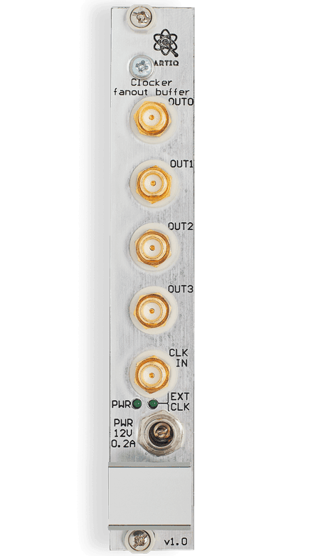
Clocker
Main Function: Distributes a low-jitter clock signal to multiple EEM devices
Typical Use Case: Precise clock distribution and synchronization in experiments
Supported Devices: Any modules requiring a stable reference clock
Interface / Connectors: Inputs: 2 (SMA, MMCX) Outputs: 10 (4 SMA, 6 MMCX)
Signal Type: Clock / timing signal
Frequency / Speed: Up to 1 GHz
Processing Location: Signal distribution only
ARTIQ Support: Used as clock infrastructure within ARTIQ setups
Form Factor: 3U EEM module
Power: 12 V from EEM or front-panel DC jack
Special Features: Low jitter <100 fs RMS; hybrid ground strategy to avoid ground loops
Connector Options: SMA and MMCX
Adapters (SMA_IDC / BNC_IDC / MCX_BNC)
Main Function: Breakout adapters that route IDC connectors to standard RF connectors
Typical Use Case: Connecting DAC/ADC modules (Zotino, Fastino, Banker, Stabilizer) to external equipment
Supported Devices: Zotino, Fastino, Banker, Stabilizer modules
Interface / Connectors: Converts IDC26 connectors to SMA or BNC connectors
Signal Type: Analog or digital signal breakout
Frequency / Speed: Depends on connected module
Processing Location: Passive routing adapter
ARTIQ Support: Used with ARTIQ DAC/ADC modules
Form Factor: Front-panel adapters (4HP or 8HP)
Power: Passive (no power required)
Special Features: Allows flexible connector types and panel density
Connector Options: SMA-IDC (8 SMA), BNC-IDC (8 BNC), MCX-BNC adapter option
Panel Space: BNC version: 8HP panel; MCX version: 4HP panel (more compact)
Power Supply (200W Power Module)
Form factor: 4" × 2" compact PCB design
Output power: 140W (convection), 200W (forced air cooling)
Input voltage range: 80–264 VAC
Output voltage options: 12V to 48V
Efficiency: Up to 95%
No-load power consumption: < 0.5 W
Leakage current: < 130 μA
Cooling:
Convection cooling or forced air, Integrated fan supply: 12V / 0.5A
Protections: Short circuit, Overload, Overvoltage, Overtemperature
Lifetime (MTBF): > 65,000 hours
Operating altitude: Up to 5000 m
Cassing
Soon
Cables
Soon
ARTIQ Software
ARTIQ (Advanced Real-Time Infrastructure for Quantum Physics) is a modern control system for quantum computing experiments, developed in collaboration with a growing international network of research institutions. It provides a high-level programming environment based on Python for describing complex experiments, which are then compiled and executed on dedicated hardware with nanosecond timing resolution and sub-microsecond latency.
International Sinara Community
Most of the hardware was designed by the Warsaw University of Technology, with a significant portion of development and testing carried out by Creotech Quantum. Integration with ARTIQ is supported by M-Labs and QUARTIQ.
Ongoing development is funded in part by organizations including NCBR (Poland’s National Centre for Research and Development), the United States Army Research Laboratory (ARL), Duke University, the University of Oxford, the University of Oregon, and the University of Freiburg (Albert-Ludwigs-Universität).
Peripheral devices compatible with Sinara modules are supplied by international partners such as M-Labs, ARL, the University of Oxford, the University of Maryland, and the National Institute of Standards and Technology (NIST) in Boulder. All designs are released under the CERN OHL v1.2 open-hardware license.
Sinara Ecosystem
Category
Product name
Function
Channels
Frequency range
/ BW
Converter
Resolution
FPGA
Front panel connectorsNotes
Notes
Controller
Kasli SoC
System controller
12
N/A
N/A
N/A
Xilinx Artix-7 (XC7A100T)
SFP cage (WR), RJ45 Ethernet, USB Type-B
RTIO core
Controller
Kasli SoC
System controller
12
N/A
N/A
N/A
Xilinx Artix-7 (XC7A100T)
SFP cage (WR), RJ45 Ethernet, USB Type-B
FPGA + ARM
Timing & Sync
Clocker
Clock distribution
ref clk up to 125 MHz
N/A
N/A
Xilinx Artix-7 (XC7A35T)
SMA female (clk I/O), SFP cage (WR)
Low-jitter timing
Interface modules
Grabber
High-speed digital interface
device-dependent
N/A
N/A
Xilinx Artix-7 (XC7A35T)
HD-68 female
Digital interface
Digital
DIO BNC
Digital input/output
8
up to 100 MHz
N/A
N/A
N/A
BNC female ×8
TTL I/O
DIO SMA
Digital input/output
8
up to 100 MHz
N/A
N/A
N/A
SMA female ×8
TTL I/O
FAQ
Most modules are available off the shelf. Delivery times for integrated systems are determined individually but typically do not exceed a few weeks.
Yes. We provide custom calibration tailored to the specific requirements of your experiment or system.
Yes. The modules are designed for fast and straightforward integration with standard lab setups and existing infrastructure.
Yes. We support our clients at every stage — from module selection and integration to full system commissioning.
Yes. All our products include a one-year hardware warranty.